Ac Motor Brush Field Armature Wiring Diagram Typical Brushed
[diagram] motor wiring diagram 3 phase 12 wire thermal leads Shunt wound dc motor wiring diagram Ac and dc generator diagram
[DIAGRAM] 12 Lead Ac Motor Wiring Diagram Picture - MYDIAGRAM.ONLINE
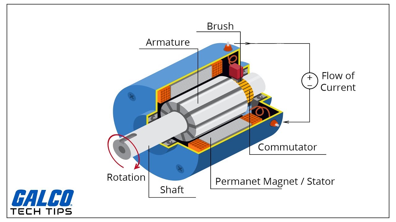
Motor section brushed electrical typical cross inside engineering dc electric parts motors permanent magnets books asynchronous three phase stator rotor Pole motors magnets electrical stepper magnetism wiring induction armature rpm conventional electromagnetic pwm torque rotate 115 volt ac single phase motor armature and fields wiring diagram
Ac motor armature
Dual voltage motor wiring diagram photo index 12 volt dc reversingMotor armature winding traction General electric commercial washer wiring diagramDon't ignore the humble brushed dc motor.
Dc motor field structure and armature assembly115 volt ac single phase motor armature and fields wiring diagram Armature winding and field windingMotor diagram ac commutator electrical armature circuit repulsion schematics input excited fig line contractor.

Brushless brushed hpi
The wiring diagram of motors and batteries. both motor controllers are[diagram] 12 lead ac motor wiring diagram picture How does a brushless ac motor workMotor ac diagram wiring armature phase single machine universal washing field fields volt wire circuit motors schematic figure capacitor pmg.
Ac brush motor wiring diagramBrushless dc motor explained What is universal motor? how it works?Dc motor armature winding diagram.
Electronic – reversing direction of an ac universal motor – valuable
Dynamic model of a permanent magnet dc motorAlternator is also called as generator at craig melton blog Electric generator: a basic introduction to how generators work, theirAc brush motor wiring diagram.
Brushless dc motor vs. ac motor vs. brushed motorBrushless electric motor diagram Electrical and electronics engineering: brushed dc motorHow does a brushless dc motor work.
Schematics for: commutator type motors
Armature winding principle commutator explanation etechnophilesWinding armature difference windings Wiring motor volt phase single diagram 115 ac armature fields field rotor coils conductor revolving circuitLeeson dc motor wiring diagram.
Schematics for: commutator type motorsSingle phase motor wiring diagram and examples Motor ac commutator electrical motors diagram circuit universal series dc type schematics connected compensated fig part contractorTypical brushed motor in cross-section.
![[DIAGRAM] 12 Lead Ac Motor Wiring Diagram Picture - MYDIAGRAM.ONLINE](https://i2.wp.com/i.stack.imgur.com/efCmT.png)
Motor universal direction current eltra trade will torque clockwise rotor begins counterclockwise unidirectional rotate therefore turn action way also dc
Dc motor working principle, construction and diagram explanationMotor brushed dc ac brushless motors basics vs gear construction structure electric video between Ac and dc motor diagram in animation.
.


Brushless DC Motor vs. AC Motor vs. Brushed Motor

Dual Voltage Motor Wiring Diagram Photo Index 12 Volt Dc Reversing

Shunt Wound Dc Motor Wiring Diagram

Dc Motor Armature Winding Diagram - General Wiring Diagram

Leeson Dc Motor Wiring Diagram - diagram lungs

Ac Brush Motor Wiring Diagram

115 Volt Ac Single Phase Motor Armature And Fields Wiring Diagram